How to Avoid Voltage Drop with 2.5 mm² and 4 mm² Copper Wires
Voltage drop is a critical concern in electrical installations, as excessive drop can lead to reduced efficiency, equipment malfunction, or safety hazards. For 2.5 mm² and 4 mm² copper wires commonly used in household and light commercial wiring, minimizing voltage drop ensures optimal performance. This guide provides a structured approach to avoiding voltage drop, including calculations, best practices, and practical considerations, presented in a formal and professional manner.
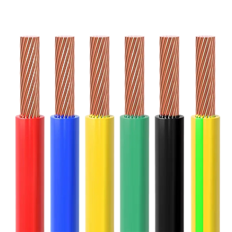
Table of Contents
1. Understanding Voltage Drop
Voltage drop refers to the reduction in voltage between the power source and the load due to the resistance of the conductor. In household wiring, the acceptable voltage drop is typically limited to 3% for lighting circuits and 5% for other circuits to ensure efficient operation and compliance with standards. Excessive voltage drop can cause dimming lights, overheating, or reduced equipment lifespan. For 2.5 mm² and 4 mm² copper wires, proper sizing, circuit design, and installation practices are key to minimizing voltage drop.
2. Characteristics of 2.5 mm² and 4 mm² Copper Wires
These copper wires are commonly used for low-voltage (e.g., 300/500 V or 450/750 V) household wiring, with the following specifications:
- 2.5 mm² Copper Wire:
- Ampacity: Approximately 25 A at 60°C (PVC insulation), suitable for power outlets and general circuits.
- Resistance: 7.41 Ω/km at 20°C for copper conductors.
- Applications: Lighting circuits, power outlets, small appliances.
- 4 mm² Copper Wire:
- Ampacity: Approximately 34 A at 60°C, suitable for high-power appliances.
- Resistance: 4.61 Ω/km at 20°C for copper conductors.
- Applications: Air conditioners, ovens, sub-main circuits.
- Conductor Type: Solid (Class 1) for fixed installations or stranded (Class 2 or 5) for flexibility.
- Insulation: Typically PVC (70°C rating) or XLPE (90°C rating) for household use.
- Voltage Rating: 300/500 V or 450/750 V, compatible with standard AC household circuits.
| Specification | 2.5 mm² | 4 mm² |
|---|---|---|
| Ampacity (60°C) | ~25 A | ~34 A |
| Resistance (20°C) | 7.41 Ω/km | 4.61 Ω/km |
| Applications | Outlets, lighting | High-power appliances |
3. Voltage Drop Calculation
Voltage drop is calculated using the formula:
VD = (2 × I × L × R) / V × 100
- VD: Voltage drop (%).
- I: Current (A).
- L: One-way cable length (m).
- R: Conductor resistance (Ω/km).
- V: System voltage (V, typically 230 V for single-phase household circuits).
Note: The factor of 2 accounts for the round-trip length (positive and negative conductors).
Example Calculations:
- 2.5 mm² Wire: For a 20 A load over 15 m on a 230 V circuit:
- VD = (2 × 20 × 15 × 7.41) / 230 × 100 ≈ 1.93% (acceptable, <3% for lighting).
- 4 mm² Wire: For a 30 A load over 20 m on a 230 V circuit:
- VD = (2 × 30 × 20 × 4.61) / 230 × 100 ≈ 2.40% (acceptable).
- Excessive Case: For 2.5 mm² with 20 A over 30 m:
- VD = (2 × 20 × 30 × 7.41) / 230 × 100 ≈ 3.86% (exceeds 3%, consider 4 mm²).
| Wire Size | Load (A) | Length (m) | Voltage Drop (%) | Acceptable |
|---|---|---|---|---|
| 2.5 mm² | 20 | 15 | 1.93 | Yes (<3%) |
| 4 mm² | 30 | 20 | 2.40 | Yes (<3%) |
| 2.5 mm² | 20 | 30 | 3.86 | No (>3%) |
4. Strategies to Avoid Excessive Voltage Drop
To minimize voltage drop with 2.5 mm² and 4 mm² copper wires, implement the following strategies:
- Select Appropriate Wire Size:
- Use 2.5 mm² for loads up to 25 A and shorter runs (<15 m) to keep VD <3%.
- Choose 4 mm² for higher loads (up to 34 A) or longer runs (15–25 m) due to lower resistance.
- Example: For a 20 A load over 30 m, switch from 2.5 mm² (VD ≈ 3.86%) to 4 mm² (VD = (2 × 20 × 30 × 4.61) / 230 × 100 ≈ 2.40%, acceptable).
- Minimize Cable Length:
- Optimize circuit design to reduce the distance between the power source and load.
- Place distribution boards or sub-panels closer to high-power loads (e.g., air conditioners).
- Reduce Load Current:
- Distribute loads across multiple circuits to lower the current per wire.
- Example: Split a 30 A load into two 15 A circuits, each using 2.5 mm², to reduce VD.
- Use Higher Voltage Systems:
- Where possible, use 400 V three-phase systems for high-power loads to reduce current and VD, though this is less common in households.
- Account for Temperature Derating:
- Apply derating factors for ambient temperatures above 30°C (e.g., 0.91 for 40°C) to ensure ampacity remains sufficient, as higher temperatures increase resistance.
- Example: 2.5 mm² at 40°C has a derated ampacity of 25 A × 0.91 ≈ 22.75 A.
- Ensure Proper Installation:
- Avoid bundling cables, as this increases heat and resistance; use cable trays or spacing.
- Use proper connectors and terminations to minimize contact resistance.
| Strategy | Action |
|---|---|
| Wire Size | Use 4 mm² for longer runs or higher loads |
| Cable Length | Minimize distance, use sub-panels |
| Load Current | Split loads across circuits |
| Temperature Derating | Apply factors (e.g., 0.91 for 40°C) |
5. Practical Applications
2.5 mm² and 4 mm² copper wires are used in various household applications:
- 2.5 mm²:
- Lighting circuits (10–15 A, <15 m runs, VD <3%).
- General-purpose outlets for small appliances (e.g., TVs, chargers).
- 4 mm²:
- High-power appliances (e.g., air conditioners, ovens, 20–30 A, up to 25 m).
- Sub-main circuits feeding distribution boards.
| Wire Size | Application | Max Load (A) | Max Length (m, VD <3%) |
|---|---|---|---|
| 2.5 mm² | Lighting, outlets | 20 | ~15 |
| 4 mm² | Appliances, sub-mains | 30 | ~25 |
6. Challenges and Solutions
| Challenge | Solution |
|---|---|
| Long Cable Runs | Use 4 mm² or larger, shorten runs with sub-panels |
| High Loads | Split loads, use 4 mm² for >20 A |
| High Ambient Temperature | Apply derating factors, ensure ventilation |
| Installation Errors | Use proper connectors, avoid bundling |
7. Conclusion
Avoiding excessive voltage drop with 2.5 mm² and 4 mm² copper wires requires careful calculation and strategic planning. By selecting the appropriate wire size (2.5 mm² for <15 m and <25 A, 4 mm² for longer runs or higher loads), minimizing cable length, reducing load current, and accounting for temperature effects, users can keep voltage drop below 3–5%. These practices ensure efficient, safe, and reliable electrical installations for household applications, supporting a lifespan of 25–30 years.
Source: JianYunCable.


Comments
Post a Comment