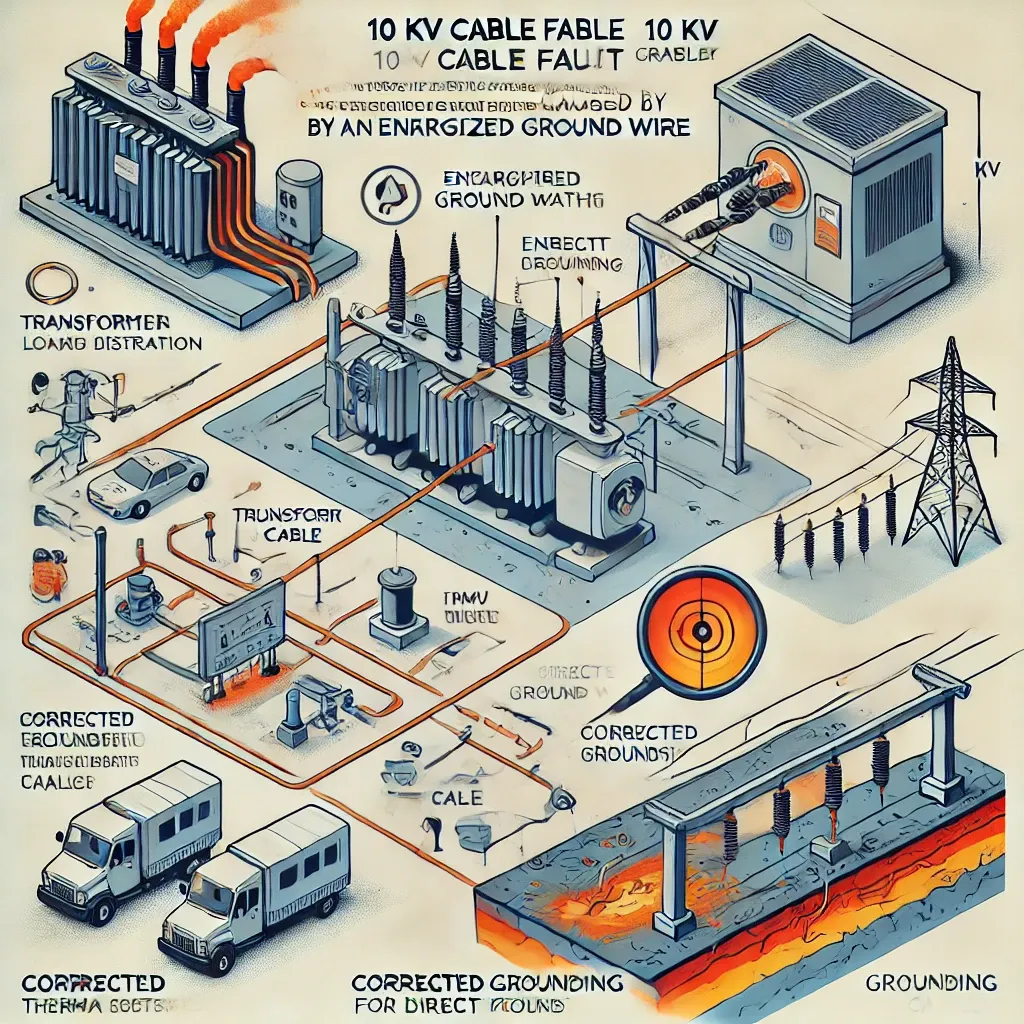
Analysis and Prevention of a 10 kV Cable Fault Caused by an Energized Ground Wire
Introduction
With the rapid expansion of 10 kV high-voltage cable networks, cable failures have become increasingly frequent. One of the less common but critical failure causes is insulation breakdown due to an energized ground wire. This study examines a real-world 10 kV cable fault, analyzes its root causes, and proposes preventive measures to ensure safe and stable operation of power distribution networks.
1. Case Study: Cable Fault Due to Ground Wire Energization
1.1 Fault Overview
- Cable Model: 10 kV YJLV22-3 × 240 mm²
- Installation Method: Combination of duct and trench laying
- Fault Location: 286 m underground cable section
- Operating History: Commissioned in August 2011
1.2 Fault Discovery and Diagnosis
Following a power outage, automated system logs identified a short circuit between phases A and B, with a fault current of 3,100 A. Insulation testing yielded the following results:
| Phase | Insulation Resistance (Ω) | Status |
|---|---|---|
| A | 0 | Faulty |
| B | 0 | Faulty |
| C | 9,700,000 | Normal |
Using fault location technology, the fault point was pinpointed at the junction between the cable and the support bracket, where the cable insulation had been punctured, exposing the core.
2. Root Cause Analysis
2.1 Investigation of Ground Wire Energization
After isolating the faulty cable and implementing temporary grounding measures, abnormal voltage signals were still detected. Infrared thermal imaging showed a localized hot spot at the grounding point, indicating a continuous current flow of 14.03 A.
Further investigation revealed:
- Neutral wire charging due to transformer imbalance – The low-voltage side of the transformer had a severe phase imbalance, leading to neutral line voltage offset.
- Poor transformer grounding – The neutral wire should discharge to ground, but due to defective grounding, current was instead flowing back through the cable armor layer.
- Improper grounding design of the ring main unit (RMU) – The RMU ground connections were incorrectly linked together before connecting to the grounding bus, causing current diversion into the faulty cable.
- Compromised cable sheath – The mechanical damage at the cable sheath created a weak point, allowing current to arc and generate heat, ultimately leading to insulation breakdown.
2.2 Current Flow Path in the Fault Condition
- Transformer neutral point → Incomplete ground discharge → Backflow into 10 kV cable armor → RMU grounding system
- Excessive current buildup at weak insulation points → Thermal stress and insulation breakdown
3. Preventive Measures
| Preventive Action | Objective |
|---|---|
| Balanced Load Distribution | Prevent transformer neutral point offset and minimize neutral wire charging. |
| Proper Grounding Design | Ensure transformer and RMU grounding resistance ≤ 4 Ω, meeting national safety standards. |
| Direct Grounding for RMU Cables | Each cable should connect directly to the grounding bus rather than being linked together first. |
| Routine Infrared Inspection | Identify early-stage overheating due to abnormal grounding currents. |
| Cable Sheath Integrity Monitoring | Ensure cable sheath protection to prevent insulation failure. |
4. Conclusion
This study analyzed a real-life 10 kV cable failure caused by an energized ground wire, leading to insulation breakdown. The main issues included transformer grounding defects, RMU grounding errors, and cable sheath damage. By implementing balanced load distribution, improved grounding designs, and routine monitoring, such failures can be effectively prevented, ensuring reliable and safe operation of 10 kV cable networks.
5. Keywords
- 10 kV Cable Fault Analysis
- Ground Wire Energization
- Transformer Neutral Point Voltage
- Electrical Grounding Defects
- Preventive Maintenance in Power Distribution
6. References
- Guo Huailong, Chen Zhijie, Li Yamin (2024). Analysis and Prevention of a 10 kV Cable Fault Caused by an Energized Ground Wire. Wire & Cable, No.6, 2024. DOI: 10.16105/j.dxdl.1672-6901.202406015
- GB/T 50065-2011 – Grounding Design Code for Electrical Installations
- DL/T 664-2016 – Infrared Diagnostics for Power Equipment

Comments
Post a Comment